Repair of an Atwater Kent 55 Console
© 2010, Richard Fairbanks
|
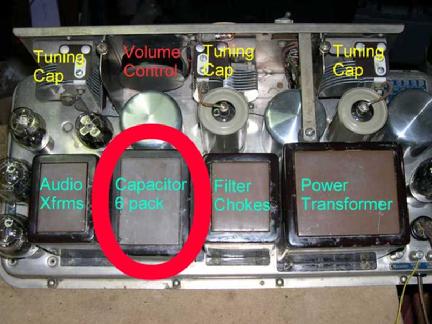
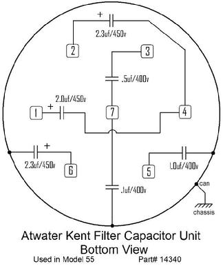
One of the big cans on the topside of the chassis contains a half dozen capacitors, including two main filter capacitors for the power supply. Antique filter capacitors are to be treated as unreliable at best; a majority have already failed and we usually replace them without a second thought. I would prefer not to open the can, though.
|
|
I have heard that Atwater Kent capacitors of this vintage have lasted better than most. Unlike early electrolytics, these are made of paper and wax that have been sealed inside a metal box ever since they were made, so I decide to test them first to see how bad they really are.
|
First I need to do a “reform” procedure by applying slowly increasing voltage for many hours. Radio-heads like me often think capacitor reforming is only for electrolytic caps,
but I swear it helps with larger value paper types too. Capacitors with 40+ years of non-use usually exhibit high amounts of current leakage when abruptly returned to service and are prone to fail quickly thereafter. A few hours of reforming, though, give many a renewed ability to hold a good
charge yet others seem to receive little or no benefit. If
these old caps will ever be useable again, reforming will help stabilize them and
possibly reverse effects of extended non-use. To my delight the two power
filtering capacitors take reforming well and hold a good charge! Four
other capacitors tucked in alongside them seem pretty good, too, with just some small
amounts of leakage. All six are in circuit positions
that can tolerate a little bit of leakage so I am going to leave them alone! The power supply will be fused to protect it if one of them
fails catastrophically in the future. Better still, I do not have to open that can!
|
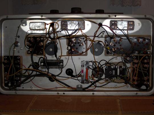
There are three smaller sealed capacitor clusters under the chassis and my luck with them is not as good. Each has at least one element that needs replacing, which requires opening each of the little cans. They are solder-sealed on the back side and must be melted open. Wax bubbles, oozes, and stinks up the place. Soon each can’s guts are removed and replaced with modern parts. I re-install the cans but this time with the backs left open. Since the open wall is against the chassis, each can’s contents remain electronically shielded . The cans are hollow shells of their former selves but look and perform like original parts.
|
The volume control is a big round thing bolted
to the front panel with seven wires coming out of it. I take it out for a
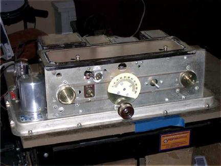
cleaning but neglect to take photos of it before reinstallation. The tuning mechanisms need attention, too. All three variable capacitors
are unmounted and pulled completely apart to receive a good scrub in the sink
with an old toothbrush. Their brass drive wheels are black with age. I
should not care about how their wheels look.They will be completely hidden when the radio is assembled, but
I just cannot help myself! I shine them up, a total waste of time, but it
somehow makes me I feel better.
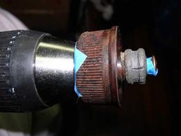
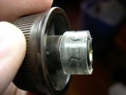
The tuning knob needs a new rubber
ring. The old one is completely dried and worn out, with a deep gulley where it engages the tuning assembly. I am not able to pull off the
old rubber so I decide to grind it down and slip a new piece over it.
|
 |
| Tuning knob mounted on a drill |
|
|
 |
| Old rubber gear is ground down |
|
|
 |
| Plastic tubing from a hardware store makes a new gear |
|
|
Mounting the knob on the end of a drill helps me grind off the
rubber evenly. Clear tubing from a hardware store then fits snugly and works
perfectly.
|
My radio chassis’ shiny new good looks are begging me to
plug it in and let it sing! Not so fast. First, that speaker field coil problem
has to be solved. You may recall that the coil works but measures around 650
ohms, not 1100 ohms. Its resistance, if it were perfect, would rise to around
1100 ohms when the coil warms up during normal operation. Some important voltages
inside the radio are determined by this value so it needs to be right.
As
mentioned earlier, I have found evidence that a previous repairman tried to
compensate for the effects of the coil’s lower value by replacing a couple of those dog bone
shaped resistors using some unique values. I have replaced those with new parts of proper values. His “fix” would have corrected voltages
immediately downstream of those resistors but not to the rest of the radio. A
better solution is to adjust the field coil itself by adding a resistor in
series with it.
|
 |
| Compensating resistor mounted on speaker |
|
The question now is where to put a new resistor. It could be hidden inside the chassis where there is plenty of space but I decide differently. The resistor will get quite warm as it dissipates several watts of heat and I would rather it radiate heat harmlessly into the open air than add extra heat under the chassis. Besides, the new resistor’s job is to compensate for this particular speaker coil. I want the chassis to operate exactly as it should even if the speaker is replaced later, so I decide the new resistor will be mounted on the speaker! I’ll include a note inside the radio about this and all my other work. Repairmen of the future should not have to guess about what I did.
next-->
|
|
|